
Developing a totally integrated control & data management system for deepwater drilling rigs

Concurrent with deepwater exploration for oil and gas are tremendous advancements in automation and control systems aboard drilling vessels.
By Trey Mebane V-ICIS Product Development Mgr.
M/D Totco Division, Varco International
Contents
Coordination can be critical
Blowouts & mud analysis
A drilling rig is a data-intensive environment with interrelated functions
The quest for a totally integrated system
PLCs at the base of the system
The structured control language of IEC 1131-3
Math requirements of oil rig vessels
Development success
The latest equipped vessels rival the technology of a NASA spacecraft. Perhaps this similarity exists for some of the same reasons. Deepwater rigs, like spacecraft, are isolated, too. Since no nearby support is readily available, they must be virtually self-sufficient.
Coordination can be critical(Back to Top)
And like a spacecraft making and maintaining critical docking tasks with costly satellite equipment, the drilling rigs must make critical positioning maneuvers relative to the wellbore thousands of feet below the ocean surface. Satellite signals fed to sophisticated dynamic positioning (DP) systems provide thruster motor responses to control the ship's position within critical tolerances, protecting the pipe string and "preserving the hole". Errors in positioning can be extremely costly in terms of equipment and a major setback to accomplishing the overall mission. Operating around the clock, any downtime can translate into a loss of US$400,000 per day.
Safety, protection of equipment, and process management are critical concerns on drilling rigs. The potential for loss of life or injury exists in addition to the commercial risks associated with rig downtime, due to equipment failure or accidents. To help manage the coordination of both equipment and process, integrated solutions of PLC (Programmable Logic Controller) controls and HMI (Human Machine Interface) workstations are a "hard" requirement.
For example, a pipe racker is a highly specialized robot to replace the roughnecks working on a rig floor. If a pipe racker should loose its grip on the pipe, or rotate the pipe or racker arms into another tool, the consequences could be costly in terms of both injury or commercial commitments.
Drilling or tripping can involve multiple pieces of equipment and systems:
All of these require precisely coordinated control between the driller, assistant driller, roughnecks and roustabouts.
Blowouts & mud analysis(Back to Top)
There are also the dangers of blowout associated with drilling. This requires careful monitoring of pressures and the existence of control systems that can quickly come into play if abnormal pressures should be encountered. Consequently, sophisticated well control schemes are a necessary part of every operation, especially in deep water.
A related area requiring constant control and monitoring is the mud system. For those readers unfamiliar with rotary drilling rigs, "mud" is the name given to the drilling fluid used in rotary drilling to maintain down hole pressure equilibrium and to remove bit cuttings from the bottom hole. Mud is being circulated continuously down the inside of the drill string through watercourses or casing in the bit, and upward in the annular space between the drill pipe and the borehole. This requires proper operation and coordination of mud pumps to transport the cuttings, especially in near-horizontal wells. At the surface, the returning mud is diverted through a series of tanks or pits which allow cuttings separation and any necessary treatment before recycling the fluid. Proper operation of this cycle requires evaluation of feedback data from several areas, including the monitoring of the chemical as well as the physical properties of the mud.
A drilling rig is a data-intensive environment with interrelated functions(Back to Top)
The list of requirements for monitoring and control on a drill ship go far beyond these few examples. It is a data intensive environment that requires constant sampling and monitoring. Control schemes, including the coordination of data from throughout the overall process, need to be well thought out. Initially, these control and monitoring systems were handled in "islands" of automation.
But just as control and monitoring systems in factories have evolved from islands to totally integrated systems, drilling rigs are now following suit. Just because multiple vendors may have supplied the various components of the overall operation, it does not preclude the need to tie everything together over a common network. For example, it is very often the case that different vendors supply the drawworks drive control and the automated pipe handling systems. But obviously these systems have to work in a coordinated fashion. The best way to handle this effectively is to have the two systems share control data over a common network. Sharing data is a starting point for developing an effective integrated system.
The quest for a totally integrated system(Back to Top)
Varco International, Inc., perhaps best known for making top drives, recently developed an integrated system called "V-ICIS" (vee-eye-sis), an acronym for Varco Integrated Control and Information System. Varco's M/D Totco Division played the lead role in writing the source code that ties all the hardware and operating systems together.
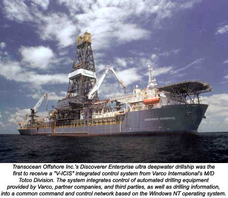
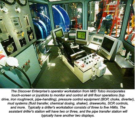
This system concept integrates control of automated drilling equipment provided by Varco, partner companies, and third parties, as well as drilling information, into a common command and control network based on the Windows NT operating system. Through touch-screen or joystick controls, drillers, assistant drillers, and other operators monitor and control all drill floor operations (top drive, iron roughneck, pipe-handling), pressure control equipment (BOP, choke, diverter), mud systems (fluid transfer, chemical dosing, shaker), drawworks, SCR controls, and more. All this is achieved from the comfort of futuristic looking control chairs. Typically a driller's workstation consists of three to five HMI's. The assistant driller's station will have two or three, and the pipe transfer station will typically have another two displays.
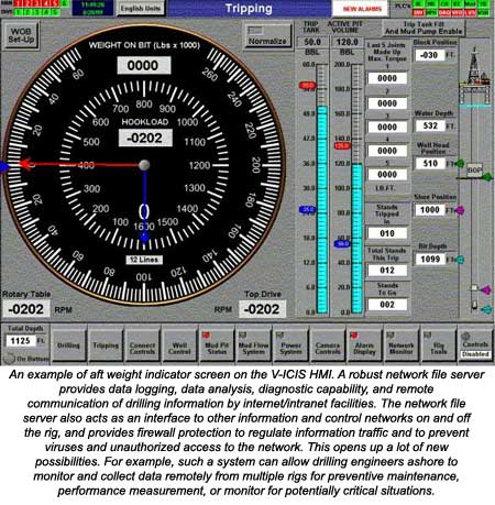
A robust network file server provides data logging, data analysis, diagnostic capability, and remote communication of drilling information by internet/intranet facilities. The network file server also acts as an interface to other information and control networks on and off the rig, and provides firewall protection to regulate information traffic and to prevent viruses and unauthorized accessto the network. This opens up a lot of new possibilities. For example, such a system can allow drilling engineers ashore to monitor and collect data remotely from multiple rigs for preventive maintenance, performance measurement, or monitor for potentially critical situations.
PLCs at the base of the system(Back to Top)
Under the V-ICIS concept, all the I/O data of the drilling rig is being handled PLCs that interface the various subsystems (hoisting, pipe handling, SCR, drilling, solids control, mud circulation/analysis, and others). If you view V-ICIS as the familiar control pyramid, then PLCs form the base with the HMI and DWS (diagnostic workstations) at the pinnacle. The file server mentioned earlier is at the heart of the system and interfaces the PLCs as a "signal router". In addition to the PLCs, it networks the HMI, DWS, SCADA, and even the vessel's DP system. Profibus or Ethernet connects the PLCs to the server, depending on the nature of the "tools" being interfaced on the other side of the PLC. HMI and DWS are interfaced via Ethernet. At the upper control level, critical positioning maneuvers require millisecond response time. Whereas Profibus can exchange data five to eight times per second, Ethernet can routinely exchange data at 90 to 150 times per second. This extra speed is required in coordinated tasks such as zone management, used to reduce the risk of tool collisions that could result in downtime or injury.
Varco has standardized to Siemens PLCs for V-ICIS. They have done this for several reasons, one of the strongest being Siemens compliance with IEC 1131-3 specifications for language platforms. Under this industry guideline, the IEC has proposed that PLC manufacturers offer five programming language options for interfacing their PLCs. These languages are Ladder Logic, Sequential Function Charts (SFC), Structured Text (ST), and Instruction Lists (IL). Anyone who has programmed PLCs is at least familiar with one of these languages.
Most PLC programmers are familiar with ladder logic, because that is usually the language of choice for most applications. When PLCs were first invented, the creators wanted a language that closely resembled the relay schematics that electricians and engineers were already accustomed to using.
Ladder logic is fine except when the configurations become highly complex and the components represented are doing a lot more than just processing off and on signals. This is especially true when the logic has to perform a large number of math algorithms or mathematical functions having more than casual arithmetic calculations to perform. What kind of relay configuration would you build to perform a trigonometric function, for example? Thus it is easy to see why other supporting languages have emerged. The example is not impossible to configure, but nearly impossible to visualize as a bank of inter-connected relays even for the most skilled ladder logic programmer.
Which language is best for "talking" to the PLCs depends on the programming application and the programmers level of experience.
Looking at Varco's corporate-wide programming manpower, the levels of programming experience and language familiarity were much greater than average. Reassignment of existing personnel among various operating companies, and even additional programmer staffing from the outside the company were certainly options to be considered when the V-ICIS programming team at M/D Totco was being assembled. However, the Siemens programming language flexibility made this unnecessary. The IEC 1131-3 compliance gave the existing staff at M/D Totco a common language platform that could be easily learned and implemented for the particular objectives at hand. This turned out to be "structured text", also known as "structured control language" (SCL). It is one of the five programming language tools available in the Siemens STEP7 PLC programming system, and it is all accomplished through an intuitive IDE running on Windows NT.
Programming between the "tools" (sensors, relays, starters, electronic drives, etc.) and PLCs was accomplished outside the integration tasks at M/D Totco by the Varco programming staff from the other Varco divisions, or third-party companies, supplying the equipment (There are a total of five Varco divisions supporting the V-ICIS Group). Programming between the central server of V-ICIS and the PLCs required no understanding of the ladder logic programming used for each of the subsystems. Merely knowing the data block addresses for data storage inside the PLCs was totally adequate. The block addresses are utilized by inserting them in the syntax of the SCL where appropriate.
The structured control language of IEC 1131-3(Back to Top)
The structured control language (a.k.a. "structured text") specified in IEC 1131-3 is a high level programming language with syntax similar to PASCAL. Many programmers, upon first hearing that the SCL of this specification is patterned after PASCAL, immediately ask why not ANSI-C or C++? After all, "C" is the most widely used structured control language in use today. Without any prior experience with PASCAL, there is often an initial resistance by hard-core "C" programmers to accept learning a "new" structured language.
Keep in mind that the IEC was trying to frame a structured language that worked well for all applications complex enough to require SCL, but covering the easiest applications to the most complex. This has to include those applications or processes that have some really heavy-duty math, i.e. transcendental functions, optimization equations, transformations, calculus, and other high level math. That has been the strong suit of PASCAL from its early inception. This kind of math, on the other hand, is not a built-in characteristic of "C", as it was never intended to handle complex math.
The syntax rules of "C" and PASCAL are considerably different too. Comparing the syntax of "C" to PASCAL is like comparing complete, grammatically correct sentences to shorthand. The rules for PASCAL are much more stringent and less forgiving. That is the price paid for its wider versatility.
Maybe the ease of handling complicated math algorithms is not a good enough reason for some to endorse such a decision to structure the language after PASCAL. It seems like a hard pill to swallow if your application has few complicated math algorithms. However, this attitude disappears soon after a veteran "C" programmer makes a quick study of the syntax. The proposed language only has about 40 keywords, and 10 different statements to learn. And once you become accustomed to the more stringent rules, it is an easy and flexible language to use. Most can master its use in just a few days of writing and testing code.
Math requirements of oil rig vessels (Back to Top)
Oil and gas engineers don't have to be convinced as to the large amount of complicated math involved. The math for the hydraulics of oil and gas exploration alone are enough to scare the average person; fluid flow calculations can be quite complicated. The math used for computing pressure drops across bit nozzles and watercourses are a nightmare for instruction list programming, requiring hundreds of lines of coding. However, using these calculations to set up algorithms that might be used to compute minimum and maximum parameter alarm ranges for fluid pressure are an easy task for SCL of IEC 1131-3. The equations can generally be handled with as little as one line of code that pretty much spells out the equation, as one would see it written in a textbook—compared to a usual 12 lines of code that merely have the assignment of multiplying two numbers together using instruction list (IL) programming.
Development success(Back to Top)
The V-ICIS Group of Varco was formed in late 1997. The first totally integrated system was configured and successfully tested less in than eight months. Transocean Offshore Inc. awarded the first official order in 1999 for their Discoverer Enterprise ultra deepwater drillship located in the US Gulf of Mexico, being leased by BP/Amoco.
Two more orders by Transocean for their Discoverer Spirit and Discoverer Deep Seas are scheduled for installation.